
The Most Comprehensive Guide to Switchgear and Related Electrical Components: Practical and Powerfu
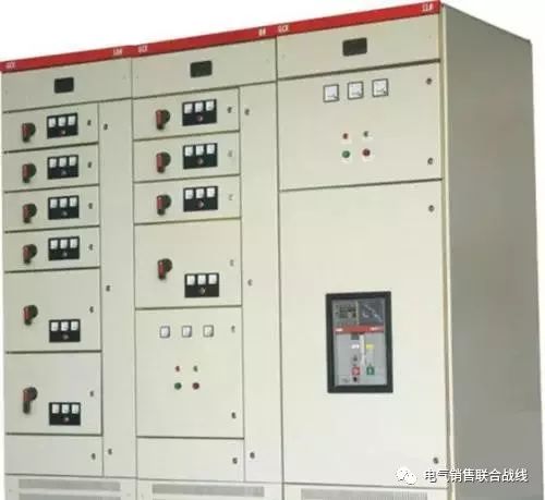
Internal components include: busbars, circuit breakers, conventional relays, integrated relay protection devices, metering instruments, disconnect switches, indicator lights, and grounding switches.
Classified by application:
(1) Infeed Cabinet: Also known as the power receiving cabinet, it is equipment used to receive electrical energy from the grid (from the incoming line to the busbar). It is typically equipped with components such as circuit breakers, CTs, PTs, and isolating switches.
(2) Feeder Cabinet: Also called the feeder distribution cabinet or distribution cabinet, it is equipment used to distribute electrical energy (from the busbar to various outgoing lines). It is also typically equipped with components such as circuit breakers, CTs, PTs, and isolating switches.
(3) Busbar Tie Switchgear: Also known as busbar disconnect switchgear, it connects two busbar sections (from busbar to busbar). Busbar ties are frequently used in single-busbar sectionalized and double-busbar systems to enable users to select different operating modes or ensure selective load shedding during faults.
(4) PT Cabinet: Voltage transformer cabinet, typically mounted directly on the busbar to monitor busbar voltage and implement protection functions. Internally, it primarily houses voltage transformers (PT), disconnect switches, fuses, and surge arresters.
(5) Isolation Switchgear: Used to isolate busbars at both ends or to separate power receiving equipment from power supply equipment. It provides operating personnel with a visible endpoint for convenient maintenance and repair operations. Since isolation switchgear lacks the capability to interrupt or connect load currents, its drawers must not be pushed or pulled when the associated circuit breaker is closed. In typical applications, interlocks between the circuit breaker's auxiliary contacts and the isolating drawer must be installed to prevent operator errors.
(6) Capacitor Cabinet: Also known as a compensation cabinet, it is used to improve the power factor of the power grid, or for reactive power compensation. Its primary components include groups of capacitors connected in parallel, switching control circuits, and protective devices such as fuses. Typically installed alongside incoming switchgear, one or multiple capacitor cabinets may operate in parallel. After disconnecting the capacitor cabinet from the grid, components inside—especially capacitor banks—require time to discharge. Direct manual contact is prohibited. For a specified period after de-energization (determined by capacitor bank capacity, e.g., 1 minute), reclosing is forbidden to prevent overvoltage damage to capacitors. When performing automatic control functions, ensure reasonable distribution of switching cycles among capacitor banks to prevent imbalance where one bank experiences frequent switching while others remain idle.
(7) Metering Cabinet: Primarily used for measuring electrical energy (kilowatt-hours), it is categorized into high-voltage and low-voltage types. Typically equipped with disconnect switches, fuses, CTs, PTs, active energy meters (traditional or digital), reactive energy meters, relays, and other auxiliary secondary devices (e.g., load monitors).
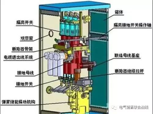
(8) GIS Cabinet: Also known as a gas-insulated switchgear cabinet, it integrates circuit breakers, disconnect switches, grounding switches, CTs, PTs, surge arresters, and busbars within a metal enclosure. It utilizes gas with excellent insulation and arc-quenching properties (typically sulfur hexafluoride, SF6) for phase-to-phase and phase-to-ground insulation. Suitable for high-voltage and high-capacity power grids, it serves for power distribution and control.
(9) Circuit Breaker: Under normal operating conditions, the circuit breaker remains closed (except for special applications), maintaining circuit continuity. During automatic control or protective control operations, the circuit breaker can open or close circuits under the control of integrated protection devices. Circuit breakers not only handle normal load currents but also withstand short-circuit currents (several to dozens of times the normal operating current) for a limited duration. They can interrupt short-circuit currents to isolate faulty lines and equipment. Thus, their primary functions are circuit interruption and connection (including normal current handling and short-circuit current interruption). During circuit breaking and closing operations, an electric arc inevitably forms between the moving and stationary contacts of the circuit breaker. To protect the contacts, minimize contact material wear, and ensure reliable circuit interruption, measures must be taken to extinguish the arc as quickly as possible. One such measure involves filling the gap between the moving and stationary contacts with different arc-quenching media. Based on the arc-quenching medium, circuit breakers can be classified into: oil circuit breakers (multi-oil, low-oil), sulfur hexafluoride (SF6) circuit breakers, vacuum circuit breakers, air circuit breakers, etc. The primary primary equipment we frequently encounter in high and low voltage switchgear during engineering projects is the circuit breaker. Since the moving and stationary contacts of a circuit breaker are typically enclosed within a container filled with arc-quenching medium, the breaker's open or closed state cannot be directly determined. Instead, it is usually identified through auxiliary devices (such as position indicators).
(10) Isolating Switch: An isolating switch (or disconnect switch) features a visible break point to indicate connection or disconnection. Primarily used to isolate high-voltage power sources, it ensures safe maintenance of lines and equipment. It can only interrupt very low currents (typically only a few amperes). Without dedicated arc-extinguishing devices, it cannot interrupt fault currents or normal operating currents and must not be operated under load.
(11) Fuse: A fuse is a simple circuit protection device. Its principle is that when the current flowing through it reaches or exceeds a predetermined value for a certain duration, its internal fuse element melts, interrupting the circuit. Its operating principle is straightforward and installation is convenient. It is generally not used alone but primarily in conjunction with other electrical devices. Key operational characteristics: First, the current must reach a specific value, which is factory-set and cannot be altered; Second, after reaching the set current value, a predetermined time must elapse before tripping occurs. This time is also factory-set and non-adjustable, though various types exist, including time-delay, fast-acting, and ultra-fast-acting fuses. Third, the fuse body is destroyed upon tripping and cannot be reused, requiring replacement. Fuse tripping can be detected via a fuse indicator or by visual inspection of the fuse element. Common fuses and fuse links fall within this category.
(12) Load Switch: A load switch incorporates a simple arc-extinguishing device, typically using air as the extinguishing medium. It can connect and disconnect normal currents and overcurrents but cannot interrupt short-circuit currents and should not be used to clear short-circuit faults. Therefore, load switches must never be used as a direct substitute for circuit breakers. If a load switch is employed, it must be used in conjunction with the high-voltage fuse mentioned earlier (in practice, fuses and load switches are often connected in series for basic overload protection to reduce project costs). Similar to disconnect switches, load switches have a distinct open gap, allowing easy visual confirmation of whether the circuit is closed or open.
(13) Transformers:
Simply put, a transformer is a device that utilizes alternating electromagnetic fields to convert between different voltage levels (effectively transforming electrical energy), with no change in frequency before and after conversion. They can be categorized by application, such as power transformers, rectifier transformers, voltage regulators, isolation transformers, as well as CTs and PTs. Power transformers are the most commonly encountered type in engineering sites.
(14) Key technical parameters related to transformers include:
❶ Rated Capacity: The transformer's rated output capability under standard operating conditions (equal to U × I, measured in kVA);
❷ Rated Voltage: The terminal voltage value under no-load and rated tap conditions (i.e., primary and secondary side voltage values);
❸ No-load loss: Losses incurred by the transformer under no-load conditions (also known as iron loss);
❹ No-load current: The current flowing through the primary winding under no-load conditions;
❺ Short-circuit loss: Losses generated when the primary side carries rated current and the secondary side is short-circuited (primarily due to winding resistance);
❻ Concept of Tap (Tap Position): To accommodate grid operation requirements, most transformers feature taps on the high-voltage side. These tap voltages are expressed as percentages of the rated voltage, known as tap voltages. For example, a 10kV high-voltage transformer with ±5% taps can operate at three voltage levels: 10.5kV (+5%), 10kV (rated), and 9.5kV (-5%). Generally, on-load tap-changing transformers feature more tap positions (tap points), such as 7-tap (±3×2.5%) or 9-tap (±4×2%) configurations. Since synchronous switching of tap changers cannot be fully guaranteed, on-load tap-changing transformers are typically not suitable for parallel operation.
❼ Active Load: Loads in a power system that generate mechanical or thermal energy. Pure resistive loads consume only active power, such as electric heating, electric furnaces, and lighting, which are entirely active loads. Induction motors and synchronous motors consume both active and reactive power; the portion that performs work to generate mechanical energy constitutes the active load. Active loads must be supplied by the active power generated by generators.
❽ Reactive Load: The non-working portion within electrical loads. Reactive power is consumed only by inductive loads, such as transformers, motors, air conditioners, and refrigerators. Therefore, while generators output active power, they must also provide reactive power. When reactive power demand exceeds grid capacity, system voltage drops. To meet user requirements, substations install reactive power compensators to maintain reactive power balance and stabilize voltage levels.
❾. Emergency Reserve: A component of power system reserve capacity. To ensure power facility safety against temporary or permanent generator failures affecting supply, systems must maintain a designated quantity of emergency reserve power sources.
❿ System Decoupling: A measure to prevent system loss of synchronism and accident escalation by dividing an intact power system into several independent systems that no longer operate synchronously. After decoupling, certain local systems may experience power shortages, frequency drops, and voltage sags. Therefore, partial load shedding is required to prevent disruption of the entire system's stability.
(15) PT(TV)/CT(AV):
Transformers of measurement (PT/TV) and current (CT/AV) are essentially specialized transformers primarily used to electrically isolate primary circuits from control circuits, thereby expanding the application scope of secondary equipment (instruments, integrated protection devices, etc.). Using PT/CT prevents high voltages/large currents from the primary circuit from directly entering secondary control equipment (e.g., instruments, integrated protection devices), and also prevents control equipment failures from affecting primary circuit operation.
❶. Characteristics of Current Transformers (CT, AV): The primary winding N1 features thicker, fewer turns, while the secondary winding N2 has finer, more numerous turns. The rated secondary current I2 is typically 5A (the primary current I1 can be approximated using N1I1=N2I2, or a CT with the appropriate turns ratio can be selected based on the primary current I1). During operation, both the primary and secondary windings of a CT are connected in series with the primary circuit and secondary control circuit, respectively. Based on the transformer characteristic U₁I₁ = U₂I₂, the operating voltage on the secondary side can be determined. This voltage becomes extremely high when open-circuited, making it absolutely impermissible to open the CT circuit. Based on application, CTs are typically categorized into protective and measuring types. Measuring CTs saturate during primary short-circuit faults to limit excessive secondary current (I2), thereby protecting integrated protection devices. In contrast, protective CTs must not trigger protection during primary short-circuit faults to ensure reliable operation of integrated protection systems.
❷ Turns Ratio: The ratio of turns in the high-voltage winding to those in the low-voltage winding of a transformer is termed the turns ratio. This can be approximated by the ratio of the high-voltage to low-voltage rated voltages. 3. Voltage Transformers (PT, AV) are characterized by: a high number of turns N1 in the primary winding and a low number of turns N2 in the secondary winding, functioning as a step-down transformer (with a typical secondary rated voltage of 100V). During operation, both the primary and secondary windings of the PT are connected in parallel to the primary circuit and secondary control circuit voltage coils, respectively. Due to the high impedance of the voltage coils, the current in the PT secondary side is extremely low, causing the secondary winding to operate in a near-no-load state. However, the secondary winding itself has very low impedance. Therefore, if the secondary winding is short-circuited, it will result in an extremely high secondary-side current (N1I1=N2I2). Therefore, the secondary winding of a PT must never be short-circuited.
(16) Drawout/Drawer: Drawouts and drawers are components of high-voltage switchgear and low-voltage switchgear, respectively, housing high-voltage circuit breakers, low-voltage circuit breakers, and associated relay components. This distinction gives rise to withdrawable switchgear (high-voltage) and drawer-type switchgear (low-voltage). Their functions are essentially identical to fixed switchgear, with the primary difference being enhanced maintenance and inspection convenience (both withdrawable units and drawers can be pushed in or pulled out using a mechanical operating mechanism crank). Drawers and pull-out units typically have three position states: operational (during normal operation), test (for trial operation and on-site testing), and withdrawn (for maintenance and repairs).
(17) Earthing Switch: The earthing switch (also called an earthing knife switch) serves two primary functions: First, it provides grounding during line and equipment maintenance to ensure personnel safety. Second, it can be used to artificially create a ground fault in the system for control and protection purposes. The first function is straightforward and requires no further explanation. The second function operates as follows: Typically connected to the high-voltage side of a step-down transformer, the grounding switch automatically closes upon faults at the receiving end or internal transformer failures. This creates an artificial ground fault short circuit, forcing the feeder-end (upper-end) circuit breaker to trip rapidly and isolate the fault. Thus, this is an intentionally induced ground fault short circuit designed to ensure swift operation of the feeder-end circuit breaker.
(18) Master Control Devices: Master control devices are mechanically operated control elements that issue commands to various electrical systems. They facilitate signal conversion and transmission within systems. Common examples include changeover switches, pushbuttons, rotary switches, position switches, and indicator lights.
(19) Contactor: A contactor is an electrical device used for frequent remote switching of AC/DC main circuits and high-capacity control circuits. Its primary control targets include motors, lighting, and capacitor banks. It is categorized into AC contactors and DC contactors. Compared to circuit breakers, its differences lie in: extremely high operating frequency (thus requiring sufficiently long electrical and mechanical lifespans); they possess higher breaking and making capacities, but are generally used at voltage levels of 1kV and below, unable to match the tens or hundreds of kilovolts handled by circuit breakers.
(20) Relays: Relays are electrical devices used to control other equipment (typically primary electrical main equipment) within control circuits, or to provide protection and signal conversion in main circuits. They are only suitable for remotely switching small-capacity control circuits, such as AC/DC current relays, voltage relays, time relays, intermediate relays, thermal relays, etc.
(21) Testing
Common tests include:
❶ Type Tests: Tests conducted on one or more devices or equipment manufactured according to specific design requirements to verify compliance with established standards.
❷ Routine Tests: Also known as factory tests, these are performed on each device or piece of equipment during manufacturing or upon completion to determine conformity with specified standards.
❸ Medium Tests: A collective term for various tests evaluating the electrical properties of a medium, including insulation, electrostatic, and withstand voltage tests.
❹ Sampling Tests: Tests performed on randomly selected samples from a batch of products to determine whether the samples meet a specific standard.
❺ Durability Tests: Tests to determine the potential lifespan of a product under specified conditions, or tests conducted to evaluate and analyze the product's lifespan characteristics. These are destructive tests.
❺ Endurance Testing: Tests conducted under specified conditions, including specific operations performed for a defined purpose within a set timeframe. Examples include repeated operations, short circuits, overvoltage, vibration, and shock. These tests are destructive.
❻ Commissioning Testing: Tests performed on products at the installation site to verify correct installation and normal operational function.